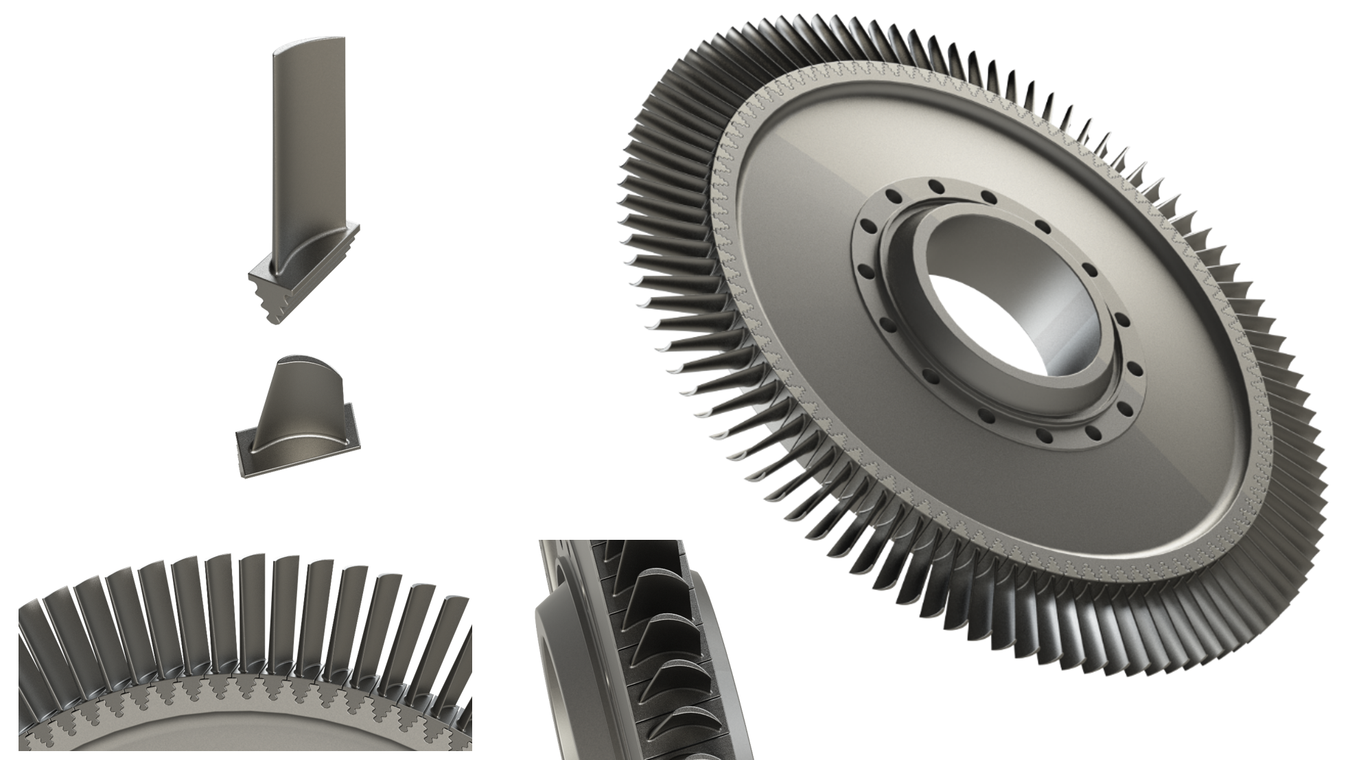
LPT Blade & Disc Design - Part 1
Low-Pressure Turbine Blade & Disc Design
Full Engineering Study - Part 1: CAD Modelling in CATIA V5
Carlos Muñoz Serrano – Mechanical & Project Engineer
1. Introduction
The design of gas turbine blades is one of the most demanding engineering challenges in the aeronautical industry. These components operate under extreme conditions, high temperatures, elevated rotational speeds and repeated cyclic loads, and must meet strict requirements for structural integrity and fatigue life over thousands of hours of operation. This project develops a complete CAD model of a low-pressure turbine (LPT) blade and disc following design criteria as close as possible to those applied in industry. The geometric reference is the turbine rotor of the Orenda Mark 14, a Canadian turbojet of 7,200 lbs thrust that powered the Canadair Sabre in the 1950s. This engine is particularly relevant because it employs a fir tree root in its LPT blades, the same joint type adopted in this project and the standard in high-pressure turbines and high-thrust engines today. All 3D modelling has been carried out in CATIA V5, combining Generative Shape Design for the aerodynamic surfaces and Part Design for the structural elements. The structural analysis, documented in Part 2, will be performed in ANSYS Mechanical.
Note on industrial context and project scope. The present project follows the logic and structure of the design processes applied across the industry. Unfortunately, many of the specific parameters, aerodynamic profile coordinates, fir tree root geometry, disc dimensions, are proprietary data not available in the public domain. Where industrial information is not accessible, decisions have been made using published technical literature, photographic references and geometric proportionality criteria. Each simplification is explicitly documented and technically justified. The objective is not to produce a certifiable design, but to demonstrate the ability to approach a complex aeronautical engineering problem with rigorous methodology, engineering judgement and domain knowledge.
2. Scope and design methodology
The project covers the complete design cycle of an LPT rotor: aerodynamic profile selection, 3D blade geometry, fir tree root, disc geometry, slot design and full rotor assembly. The objectives defining the scope are:
- Develop a complete CAD model of the LPT blade and disc in CATIA V5, with geometry representative of current industrial practice.
- Base all design decisions on real engine references and published technical literature, with explicit justification for each choice.
- Demonstrate the full industrial CAD workflow: 2D profile import → aerodynamic surface generation → parametric root design → disc design → assembly.
- Produce a model ready for structural analysis in ANSYS Mechanical (Part 2). In an industrial development, each of the following elements would be the result of an extensive, specialised process:
- The aerodynamic profile is obtained through hundreds of CFD simulations and linear cascade tests.
- The fir tree root geometry is mathematically optimised to maximise LCF fatigue life.
- Disc dimensions are calculated iteratively through structural analysis coupled with damage models. The present project follows the same structure and logic, applying the available resources at each stage: a NACA profile from a public database as aerodynamic reference, fir tree root parameters derived from published technical literature, and disc dimensions estimated from geometric proportionality with the Orenda Mark 14 reference. The resulting model is geometrically coherent and technically grounded, with all deviations from full industrial practice explicitly identified.
3. Blade design
3.1 Aerodynamic profile selection
The NACA 6412 profile has been adopted as the aerodynamic reference for this project, with the following characteristics:
- Maximum camber of 6% of chord. Pronounced curvature representative of an LPT blade.
- Maximum camber position at 40% of chord.
- Maximum thickness of 12% of chord. Additionally, a camber line curvature radius of 50mm has been applied to increase the profile curvature and better approximate the actual turbine profiles. The choice of NACA 6412 over the 65-series (more common in compressors) is justified by its higher camber and more representative flow turning characteristic of an LPT stage. The profile coordinates have been obtained from airfoiltools.com with a chord of 50mm, and imported into CATIA V5 via a VBA macro developed specifically for this project, which automatically generates the points and spline of the profile in the Part Design environment.
3.2 3D blade geometry
The 3D geometry has been constructed in Generative Shape Design (GSD) following the standard workflow for aerodynamic surfaces:
- Root section: Imported NACA 6412 profile, located at the blade base on the platform plane.
- Tip section: Copy of the root profile translated 150mm in the radial direction, scaled to 80% of the original chord to generate taper, and rotated to introduce aerodynamic twist.
- Multi-Sections Surface: Loft between both sections generating the aerodynamic surface, equivalent to the industrial process of generating ruled surfaces between sections at different blade heights.
- CloseSurface and conversion to solid in Part Design.
 Fig. 1 Aerodynamic surface generated in Generative Shape Design (CATIA V5)
| Parameter | Value |
|---|---|
| Profile | NACA 6412 |
| Chord (root) | 50mm |
| Chord (tip) | 40mm (~80%) |
| Aerodynamic height | 150mm |
| Twist | ~20° root-to-tip |
| Type | Free-standing (no shroud) |
3.3 Fir tree root
The fir tree root is the structurally most critical element of the blade. It is the zone where all centrifugal loads are transmitted to the disc and where LCF fatigue initiates in real operation. Unlike the dovetail, which is simpler to manufacture and sufficient for moderate loads, the fir tree root distributes the centrifugal load across multiple contact lobes, reducing the peak stress at each one and increasing the fatigue life of the assembly. It is the standard in HPT of all engines and in LPT of high-thrust engines, and the root type observable in photographic references of the Orenda Mark 14. The root has been modelled in Part Design from a parametric sketch with the following parameters:
| Parameter | Symbol | Value |
|---|---|---|
| Load flat angle | θ | 38° |
| Unload flat angle | α | 75° |
| Wedge angle | β | 12° |
| Load flat length | d | 3mm |
| Valley radius | r_valley | 2mm |
| Number of lobes | 3 | |
| Base dimensions | 60 × 24.4mm |
 Fig. 2 Parametric sketch of the fir tree root (Part Design, CATIA V5)
The valley radius is especially relevant, because it is the zone of highest stress concentration and the initiation point for LCF fatigue, analysed in detail in Part 2.A design detail that distinguishes this project from a simplified academic exercise is the incorporation of a 7° draft angle in the axial direction of the slot. Fir tree slots in real engines present a slight axial inclination, analogous to the principle of helical gears, which reduces vibration and improves load distribution at the root. This angle is clearly visible in the photographic references of the Orenda Mark 14.
 Fig. 3 Complete LPT blade with fir tree root and platform (CATIA V5)
4. Disc design
4.1 Function and geometry
The rotor disc supports and transmits the loads from all blades to the engine shaft. Unlike the blade, primarily conditioned by aerodynamics, the disc is a purely structural component whose geometry, bore, web and rim, corresponds to a trade-off between mechanical strength, fatigue life and minimum weight. The disc has been modelled in Part Design by revolution from a cross-section sketch, following the classic three-zone structure:
- Bore (hub): Central zone of attachment to the shaft; diameter 250mm, axial width 100mm.
- Web: Thinner intermediate zone connecting bore to rim; region of highest radial stress and a critical LCF fatigue zone. The web profile includes generous fillet radii at the transitions to minimise stress concentration.
- Rim: Outer zone housing the fir tree slots; outer diameter 800mm.
 Fig. 4 Disc cross-section sketch (Part Design, CATIA V5)
 Fig. 5 Rotor disc after revolution operation (Part Design, CATIA V5)
4.2 Fir tree slots
The blade insertion slots have been obtained via a Pocket operation in Part Design, using the fir tree root contour with a 0.3mm offset, the nominal assembly clearance between root and slot. The same 7° draft angle applied to the root has been incorporated in the axial direction of the Pocket, ensuring full geometric compatibility between both components. The 100 slots have been replicated via Circular Pattern, uniformly distributed around the disc perimeter.
4.3 Final disc parameters
| Parameter | Value |
|---|---|
| Outer diameter | 800mm |
| Bore diameter | 250mm |
| Rim axial width | ~110mm |
| Bore axial width | 100mm |
| Number of slots | 100 |
| Slot pitch | ~23mm |
| Slot draft angle | 7° |
| Slot type | Fir tree, 3 lobes |
 Fig. 6 Disc with fir tree slots and 7° draft angle (Part Design, CATIA V5)
5. Assembly
The complete assembly has been carried out in CATIA V5 Assembly Design. Both the blade and the disc have been modelled with their coordinate system positioned such that, upon insertion into the assembly, each component is automatically located in its correct position without requiring additional positioning constraints. This practice, standard in industrial design environments, ensures a clean assembly tree and makes components directly reusable in other contexts without manual repositioning.The blade fir tree root has been positioned in the corresponding disc slot, respecting the 7° draft angle and the 0.3mm nominal clearance. The 100 blades have been instantiated via Circular Pattern, uniformly distributed around the perimeter, completing the LPT rotor.

Fig. 7 Complete LPT rotor: 100 blades installed on the disc (Assembly Design, CATIA V5)
6. Conclusions
6.1 Summary
This project has produced a complete and technically grounded CAD model of an LPT rotor, covering from aerodynamic profile selection through to the final disc-blade assembly. The model incorporates the key geometric elements of a real LPT rotor: aerodynamic profile with twist and taper, fir tree root with parameters defined according to published technical literature, slots with draft angle, and a disc with the bore-web-rim structure characteristic of gas turbine discs.
6.2 Strengths and limitations
The principal strengths of the model are its geometric coherence with a real engine reference, the systematic justification of each design decision, and the incorporation of details, such as the axial draft angle, that distinguish it from a generic academic exercise. The full industrial CAD workflow has been followed throughout: from 2D profile import to parametric solid modelling and final assembly. The main limitations are inherent to the nature of an individual portfolio project. The aerodynamic profile has been selected from a public database rather than derived from CFD analysis. The fir tree root geometry has been defined from literature parameters and visual adjustment with photographic references, rather than through mathematical optimisation. The disc dimensions have been estimated by geometric proportionality rather than iterative structural calculation. Each of these aspects would be addressed by specialised teams over extended periods in an industrial development.
6.3 Next steps
The CAD model developed in this first part constitutes the basis for the structural validation documented in Part 2. The model will be imported into ANSYS Mechanical and subjected to structural analysis under the operating conditions of the Orenda Mark 14, evaluating the mechanical behaviour of the blade-disc assembly and identifying any critical zones that may require design review.
7. Resources and references
7.1 CATIA V5 workflow summary
| Stage | CATIA Module | Main operation |
|---|---|---|
| Profile import | Part Design / GSD | Macro VBA + Spline |
| Aerodynamic surface | GSD | Multi-Sections Surface |
| Blade solid | Part Design | CloseSurface |
| Platform | Part Design | Pad + Sketch |
| Fir tree root | Part Design | Pad + Pocket |
| Disc | Part Design | Shaft (revolution) |
| Slots | Part Design | Pocket + Circular Pattern |
| Assembly | Assembly Design | Circular Pattern |
7.2 Tools used
| Tool | Purpose |
|---|---|
| CATIA V5 - Generative Shape Design | Aerodynamic surfaces |
| CATIA V5 - Part Design | Fir tree root, platform, disc |
| CATIA V5 - Assembly Design | Rotor assembly |
| ANSYS Mechanical | Structural analysis (Part 2) |
7.3 References and further material
- Part 2 - Structural analysis in ANSYS Mechanical.
- Visual reference of the Orenda Mark 14.
- Profile coordinates: airfoiltools.com - NACA 6412
This post is Part 1 of a two-part series. Part 2 covering structural simulation in ANSYS Mechanical will be published shortly.